Wednesday, May 30, 2012
Week 9 Post
At the beginning of class next week, the group began to look into designs of what may work for the 3' span. Shortly thereafter,we began to build a 3' long bridge based off of the 2' bridge design. What we came up with was a working but somewhat disappointing bridge to our standards. We tested the design twice during the class period and ended up with a load of roughly 32-36 lbs. after a few minor tweaks. At the conclusion of both attempts, the bridge failed in the middle. If we were to include a cross section there, we would not have been able to place the weight bearing mechanism directly in the middle of the bridge span. I, as well as Gary and Izzie are expecting great achievements during Week 9's testing. I have learned a great deal of aspects of bridge designing, not only in 2-d but 3-d as well. The force distribution was a very cool process to go through since I am a very math intensive student. Having some slight background with bridge and cantilever designs back in high school really helped me prepare for what has already and is to come in the ENGR 103 course.
Tuesday, May 29, 2012
Weekly Post (week 9)
1. What you did in the prior week
In last week, I helped our group expend the bridge to 36”. I discussed how to improve the bridge maximum load of the bridge with my group mates. I observed the failing process of the bridge and tried to fix the weakest spot of the bridge.
2. What you and your teammates have agreed you'll do in the coming week
In the next week, we will take our new bridge to participate the competition two. We will finish the final report which concludes the process of developing of the bridge.
3. Major accomplishments of the week for the team
Due to the excellent performance of the design of the last bridge, we decided to follow the original design on the new bridge. We used the 2-1/8” long chord to replace the 1-1/4” long chord in the original, and used the 3-3/8” long chord replace to the 2-1/8” long chord in the original. The size of every piece of the bridge has been enlarged to the next size. It is an efficient way to expand the bridge
4. Issues that the team or you as an individual faces
We still not found out a perfect solution of the weakest spot in the middle of the bridge. What’s more, the final exams are coming and everyone is busing preparing the final. At the same time, the whole team should work efficiently to finish a high quality report.
5. You've now almost completed the bridge design process for the term. What have you learned about bridge design specifically?
I have learned how to turn a design from the 2-Ddrawing to 3-D reality. Any designs need a clear and organized plan. Knowing the constraint, and develop your design based on the constraint. It is important to understand the academic basic of the design. It could help you to find out the weakest of the design theoretically, such as the compression force applied on the bridge. However, theory is different from the reality. The design should consider many other factors beyond the theory, such as the twist of the bridge in reality.
Week 9 Post
Last week in class we used our 24" bridge as a starting point for the construction of our 36" bridge. We finished constructing the bridge and we tested it out two different times. We had a similar problem both times. The bridge kept failing in the middle, mostly on top. We did not have a triangle up there because at first we wouldn't have been able to fit the hook through the top, and then we wouldn't have been able to add any weight onto the bridge. However, at the end of class I found a way to form triangles on the top while having the hook fit through the top of the bridge. This should hopefully allow our bridge to hold more weight as it will keep the middle of the bridge more sturdy. We will make this addition during our next class. We will also be officially testing our bridge in the contest next class. We can only hope for the best. So far our 36" bridge has been able to hold 32 lbs. I am hoping we can try to near somewhere around 40 lbs this time. Holding up over 30 lbs last week though was probably our major accomplishment of the week.
I have learned a whole lot about bridges from this design lab, especially since I knew nothing about building a bridge previously. The one thing I learned the most about was compression and tension. I learned where most of the tension and compression are on the bridge and the importance of the ratios for each beam. WPBD probably taught me the most as it gave me the most information on my bridge while I was building it. This has given me great insight on how to build a bridge, and hopefully this knowledge can help me build other structures in the future.
I have learned a whole lot about bridges from this design lab, especially since I knew nothing about building a bridge previously. The one thing I learned the most about was compression and tension. I learned where most of the tension and compression are on the bridge and the importance of the ratios for each beam. WPBD probably taught me the most as it gave me the most information on my bridge while I was building it. This has given me great insight on how to build a bridge, and hopefully this knowledge can help me build other structures in the future.
Wednesday, May 23, 2012
Weekly Post (week 8)
1. What you did in the prior week
In last week, we did the truss analysis in class. Through the guide line of the online resources, we learned how to do the truss analysis using the joint method. Triangle calculation and free body diagram are the most important parts of the method of joints.
2. What you and your teammates have agreed you'll do in the coming week
In the future weeks, we will prepare for the competition 2, which is the final competition. We will record the process of competition for the final lab report.
3. Major accomplishments of the week for the team
We understand how to identify the compression force and the tension force. It will be helpful in our future bridge improvement. The online bridge designer provides an idea that the scale of the triangles greatly impacts the force working between triangles.
4. Issues that the team or you as an individual faces
We still have a lot of assignment to complete in the future two weeks. We will try to improve our bridge using what we have learned from the truss analysis. And we need to finish the A4 report which is important for our final grade.
5. You have now experienced one form of analysis. Address the following questions about it considering your Knex bridge:
• Is that method of analysis sufficient for a real bridge? If not, why not?
It is not enough for a real bridge. We discussed the difference between WPBD between real bridges before. The truss analysis of what we did just in two dimensions. But for a real bridge, it needs to be considered as three dimensions. A real bridge has to take force from wind. And the load would not only apply on the center of the bridge. Emergency situations should also be considered.
• What further would you like to analyze and what knowledge or tools might assist you?
The force applying on different material will also impact the performance of the bridge. And the force apply on joints should also be analysis the increase the performance of the gusset plates.
A3-Ye
1. Using the configuration shown in the drawing at the bottom calculate the forces in the truss members using the "Method of Joints" with h & W as defined in the constraints below. And Using the results of the previous truss analysis create a diagram similar to the one below with the forces next to the members or in a table on the diagram with member-to-member (e.g. "C-D") labels


2. Using the online Bridge Designer replicate this analysis

3. Define what you have to do to make the results of the hand analysis correspond to online Bridge Designer
The result of the online Bridge Designer is similar to the hand analysis of part one. The difference is cause by the different scale between hand analysis and online Bridge Designer. The length of the member has been given in the part 1. But the Online Bridge Designer does not have the function that calculates specific number. If the triangles of the online Bridge Designer have the same angle with the triangles in part 1, it should give the same result number.
4. Use the online Bridge Designer to model your Knex Truss

5. Define in words how you might use this type of analysis to improve the design your bridge given the testing information about Knex Joints in this web page
The weakest point of the bridge could be found by the truss analysis. Additional piece could be apply on that point and increase the maximum load of the bridge.
Tuesday, May 22, 2012
A3-Reiff
1 & 2.

The professor posted this morning that all of the units should not be in the metric unit. Currently all of my forces are measured in lbs m/s^2 as I incorrectly converted my forces from pounds to newtons above. In order to have all of my forces in the correct units of pounds I must divide the force of each member by 9.8. This will give me the correct force on each member in pounds.
3.

4. The results from the Truss Designer Program and the hand analysis are close to each other. The major problem between the two is the scaling. I was only able to use increments of 5N when defining the forces, so some of the forces were not exact in the Truss Designer program. I converted the 20 pounds of weight to newtons so it could be used with proper units in the Truss Designer program. However, the biggest problem was that the numbers were not scaled correctly between the Truss Designer program and the hand analysis. This was most likely the biggest problem encountered.
5 & 6.

The biggest difference will probably be the weight of the bridge made out of knex compared to this bridge, although this bridge is roughly the same design as our knex bridge. Last time we tested our bridge the truss that failed was in the middle of the bridge. This can be seen by looking at the analysis above. The middle is clearly under the most stress. While support could be added, that could end up adding more weight to the entire bridge, changing the calculations that were just preformed in this analysis. The best part about this analysis is that I can see where the bridge is most likely to fail, and I can figure out a way to solve this problem with my fellow group members.
Week 8 Post
Last week we listened to Professor Mitchell explain to us how to find the different forces throughout the bridge when a single weight is suspended from the middle of the bridge, like it is for our competition. After that we started working on the Method of Joints in order to complete the Truss Analysis that will be completed soon after this post. We finished most of the calculations in class, but sadly there was not enough time in class to finish all of the calculations. In the upcoming week our group plans on using the tools we have learned over the previous week plus everything we have learned in this lab so far in order to build a 36" bridge. The major accomplishment of the week last week was almost finishing the Method of Joints. That was very clutch. We are currently not having too many problems. The biggest problem we have to fix is with our bridge design. The middle sways too much and is too vulnerable, as the Truss Analysis this week has shown. I plan on supporting the middle of the bridge better to fix these crucial problems.
The method of analysis is a great step in the right direction for a real bridge, but it is not sufficient. Scaling is one big problem, and it will be discussed in greater detail in my A3 post. Also, some of the materials will weigh differently, and a different weight could be suspended from the middle. While corrections to calculations can easily fix these problems, it's a hassle and there has got to be a more efficient way to analysis the trusses and use this analysis to construct a more efficient bridge.
The method of analysis is a great step in the right direction for a real bridge, but it is not sufficient. Scaling is one big problem, and it will be discussed in greater detail in my A3 post. Also, some of the materials will weigh differently, and a different weight could be suspended from the middle. While corrections to calculations can easily fix these problems, it's a hassle and there has got to be a more efficient way to analysis the trusses and use this analysis to construct a more efficient bridge.
Week 8
During class last week, we began by listening to Professor Mitchell explain to us the technique of deriving the different forces distributed throughout the bridge with a single load suspended directly in the middle of the structure. Once his lecture was complete our group began to work with the Method of Joints videos in order to get some of our A3 homework/blog done within the class period. We got a lot done(almost all the calculations) within the rough hour and a half we had to work. Looking forward to next week, I am hoping we get to use the Truss Designer program more in order to aid our design of the 3' bridge that we will have to build for the final project. I do believe we will continue with the same design as our 2' bridge but with longer members.
A3-Vergiza
1. and 2.

3.

The results I received from the hand analysis closely relate to that of the Truss Designer program. The values are slightly off due to the inability to define specific lengths of members along with angles within the Truss Designer program. I converted to the 20 pounds of weight to Newtons of force by simply using F=ma. F=20lbs(9.81m/s^2)~196N. Within the Designer, it only allows you to set in increments of 5N so I chose 195 being the floored value of 196.
5. and 6.

Tuesday, May 15, 2012
Week 7 Post
Last week we tested out our bridge, The Love Train. Our bridge ended up holding 29 pounds of sand. We made a small adjustment by adding two beams across the bridge towards the end. Although it did not count for the competition in class, we tested it again. Surprisingly the results were much better, holding over just 47 pounds of sand. The bridge cost somewhere around $160,000. In the coming weeks our team has agreed to work on the 36" long bridge. I believe we plan on keeping the same basic design, but we want to make improvements where we failed last time. Last time the bridge was swaying from side to side, so we are going to add support to stop the bridge from swaying. This should allow the bridge to hold more sand. The major accomplishment our team had this week was adding the two beams, one on each side, that allowed our bridge to hold almost 20 more pounds of sand. This addition should help our design greatly for the future competition. In the future we may have some issues fixing the bridge so that it meets the new requirements, including being built so that cars can drive across the bridge. We may have to move a couple of beams higher so that cars can realistically drive across the bridge.
For the knex pieces, it would be nice if each piece could be analyzed like the pieces in WPBD were. For example, if I knew the ratios of compression and tension on each knex piece, I could rearrange the design, and possibly even the size of the bridge. Sadly, I do not know how I could do these calculations for each piece. But I would be more than willing to listen to ideas and try to do the calculations on my own time.
For the knex pieces, it would be nice if each piece could be analyzed like the pieces in WPBD were. For example, if I knew the ratios of compression and tension on each knex piece, I could rearrange the design, and possibly even the size of the bridge. Sadly, I do not know how I could do these calculations for each piece. But I would be more than willing to listen to ideas and try to do the calculations on my own time.
Week 7
Last week, I loaded the 'Love Train' as Gary video taped the breakage and Izzy saved me from the killer 'bar of death' and the impending doom when the bridge finally broke. Once we saw that the bridge only held about 29 lbs., we decided we could make a quick fix and attempt again... The quick fix was only an addition of two more pieces to prevent the torsion forces from bending our bridge. It ended up working ridiculously well with an outcome of ~47 lbs. held. Within the next few weeks, our group will design a 36 inch or greater bridge. A larger design of the same structure might prove to work extremely well but we'll only find out if we try. If possible, I would like to find out the strength ratios on each piece like the WPBD gives in order to improve that designated region to get the strength as close to 1.00 as possible without going over. Once we learn force distribution we will be able to do strength calculations ourselves without the use of a program.
Weekly Post (week 7)
1. What you did in the prior week
In the last week, I helped to load the 24” bridge during the test. It was an exciting experience to help “destroying” the bridge. I also helped to analysis the collapse of the bridge and try to reinforce the weakest point.
2. What you and your teammates have agreed you'll do in the coming week
In the future weeks, the length of the bridge will expand form 24” to 36”. We will keep the structure design of the bridge due to its outstanding performance. Truss analysis,A-3, would be conducted in the next week. The nature of the forces would be found out. Some small adjusting could be applied.
3. Major accomplishments of the week for the team
Our bridge did fantastic job during the second test. We added two pieces into the bridge compare to the original one. At the same time, the maximum load of the bridge increased from 29 lbs to 47lbs. It was a really big improvement. It proved that the design of the bridge is outstanding. We did not place the first position according to the spreadsheet which recoded the first time result. But the result of the second test was competitive.
4. Issues that the team or you as an individual faces
It is hard to predict the result of the bridge when it expend to 36”. A main flaw of the bridge is that it lacks enough room for the future adjustment. It is strong and compact. However, it also means that the bridge lack the room for the improvement. As individual, I have started to worry about writing the final report of the bridge.
5. Up to now the software you've used (WPBD) has provided "block box" answers, but you haven't really had any numbers associated with the Knex project. What numbers would you like to know for your Knex designs? If you have ideas about how to calculate them please give them.
After the testing of the bridge, the WPBD will give detail data about the compression and tension force work on chords. Further adjustments of the design could be made according to these numbers. However, for the Knex project, it would not automatically give the report as the WPBD. We could analysis the triangle by calculating the number of lengths and angles. Detail cacluation method could be found at the following website: http://www.jhu.edu/~virtlab/bridge/truss.htm. And an Excel spreadsheet has also been set up for the convenient reason. https://docs.google.com/file/d/0B69AvRYJR07tdUFUV1EteUZmdFk/edit
Throughout the calculation, we can find out the weakest chords in the bridge and reinforce them.
Tuesday, May 8, 2012
Weekly Post (week 6)
1. What you did in the prior week
In my bridge construction team, individual continue to work on separate bridges at the beginning of the class. I tried to build a bridge which has a wide part at the two ends of the bridge. The junction of the chords defined the possible width. Much more junctions are needed compare to the original design, accompanying the increasing of the cost. Overall, it was not a successful try of improvement.
2. What you and your teammates have agreed you'll do in the coming week
In the future of the weeks, we will focus on one bridge, and tried our best to improve it. The cost of the bridge is still very high and we want to reduce the cost in the condition that not reduces the affordability.
3. Major accomplishments of the week for the team
We determined which specific bridge to work on in the future weeks. Ed built an innovative bridge with a compact structure. The bridge simplifies the chord design and emphasizes the design of the junctions. The bridge worked well, and bore a great weight during the test.
4. Issues that the team or you as an individual faces
The stress analysis on Knex is difficult. And it would block the improvement of the bridge. And during the test, it is also difficult to observe how the chords and junctions work together with naked eyes.
5. After working with Knex for a week reread your entry of last week and state how your views of the similarities and differences have changed - if at all. If they haven't changed address the question of what you think would be the difference between working with Knex and designing a "real" bridge made of steel spanning 20'
In last week, I thought building the bridge on the WPBD would afford more possibilities than the Knex on bridge design, because the thickness of the chord could not be change with Knex. But when I started to focus working on the Knex, I realized that the diversity of junctions in Knex actually give more options for the design. In reality, I do not know someone will build a bridge which spans 20’. In reality, people would not use plastic to build bridge. Steel is a much more optimal choice compare to plastic which is easy aging. In reality, the designer should consider the horizontal force more than the Knex design. In the laboratory which is a indoor environment, does not have too much interference factors compare to the outdoor environment.
Week 6
During class in week 5, we were given time to construct more bridge designs and after a few minutes of debate the group consensus was to choose my bridge for the week 6 testing. The bridge was dubbed 'The Love Train' due to it's construct and resemblance of the train from a certain commercial. The bridge held roughly 38.66 lbs upon unofficial testing. Some cross span pieces need to be removed in order to cut costs during this upcoming week. Coming out at $171,000 exactly, the bridge exceeded expectations. No more distinction between KNEX and WPBD were established last week but I have still been utilizing the program at home in order to buff up my bridge building skills(as if they weren't amazing already).
Week 6 Post
Last week we continued to build a bridge out of knex. We chose a design that we liked and we built upon it. We named our bridge the Love Train, although it looks like it has a lot of snowflakes on it. We tested it out last week and we were surprised with the amount of weight the bridge could hold. The results were very good. In the upcoming week we plan on making the bridge cheaper without losing efficiency. The bridge had some extra pieces on it in the middle last week that were not doing anything, so we plan on taking them off, along with adding other improvements to the bridge. Our major accomplishment last week was designing a bridge that worked and was able to hold a decent amount of weight. We do face the problem of money though. Our bridge wasn't the cheapest because we chose to use a lot of smaller pieces to make the bridge more compact. We face the challenge of making our bridge cheaper while making sure that the bridge still can hold a lot of weight.
The similarities and differences between knex and WPBD from last week that I posted have not really changed. The only knowledge I have gained since is that making the bridge out of knex more compact has allowed our bridge to hold up more weight. There would be some differences between using the knex and the steel bridge. Conceptually, they should be built the same way, but due to the difference in materials, the two different bridges will need more support at different parts of the bridge.
The similarities and differences between knex and WPBD from last week that I posted have not really changed. The only knowledge I have gained since is that making the bridge out of knex more compact has allowed our bridge to hold up more weight. There would be some differences between using the knex and the steel bridge. Conceptually, they should be built the same way, but due to the difference in materials, the two different bridges will need more support at different parts of the bridge.
Tuesday, May 1, 2012
A2-Reiff
A Statement of Design Goals:
The bridge I have designed out of knex is based off of the bridge I designed on WPBD. The biggest difference though is the materials used. Therefore, I modified the knex bridge a little bit to add more support because knex pieces can't support as much weight as metal or tubes can. I do plan on modifying the bridge much more though to make it as cheap as possible while still being a working bridge.
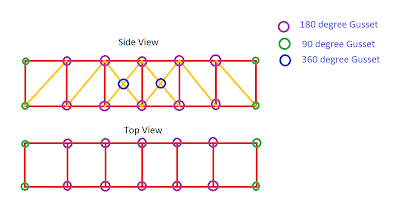
Elevation:

The bridge is made with 6 3-3/8" long chords on the top connected by 360 degree grooved gusset plates and 6 3-3/8" long chords on the bottom connected by 180 degree gusset plates. The corners are connected by 8 180 degree grooved gusset plates. The blue cross sections are made up of 4 2-1/8" long chords. They are connected with a 360 degree gusset plate in the middle. There are also 6 3-3/8" long chords going up and down that are connected by the 360 degree grooved gusset plates and the 180 degree gusset plates.
Plan:

Here the bridge is still made up of 6 3-3/8" long chords on each side connected by 360 degree grooved gusset plates on each side. The corners are connected by 8 180 degree grooved gusset plates. In between the gusset plates are 2 5" long chords, one resting on top of the 360 degree gusset plates and one connected on the bottom of the 360 degree gusset plate.
Costs:

Changes:
My bridge design kept changing as I designed more of the bridge. I kept adding more chords for support since I think it is easier to take away chords to reduce costs than it is to add chords and increase costs. I feel I have made a sturdy bridge with lots of support, but I feel like I need to find a way to cut costs and make the bridge cheaper to construct.
Learned:
During the design process I learned how to make changes on the fly that logically makes sense. I realized it is ok to make changes and vary from what the original design was. Designing the bridge is a long process that needs to keep changing if I want the bridge to be cheap and successful when it is completed.
The bridge I have designed out of knex is based off of the bridge I designed on WPBD. The biggest difference though is the materials used. Therefore, I modified the knex bridge a little bit to add more support because knex pieces can't support as much weight as metal or tubes can. I do plan on modifying the bridge much more though to make it as cheap as possible while still being a working bridge.
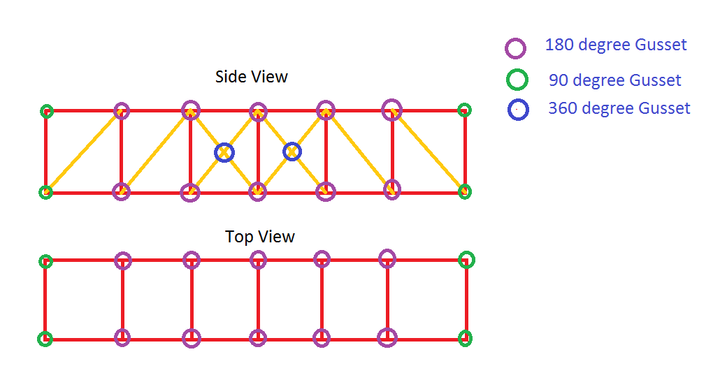
Elevation:

The bridge is made with 6 3-3/8" long chords on the top connected by 360 degree grooved gusset plates and 6 3-3/8" long chords on the bottom connected by 180 degree gusset plates. The corners are connected by 8 180 degree grooved gusset plates. The blue cross sections are made up of 4 2-1/8" long chords. They are connected with a 360 degree gusset plate in the middle. There are also 6 3-3/8" long chords going up and down that are connected by the 360 degree grooved gusset plates and the 180 degree gusset plates.
Plan:

Here the bridge is still made up of 6 3-3/8" long chords on each side connected by 360 degree grooved gusset plates on each side. The corners are connected by 8 180 degree grooved gusset plates. In between the gusset plates are 2 5" long chords, one resting on top of the 360 degree gusset plates and one connected on the bottom of the 360 degree gusset plate.
Costs:

Changes:
My bridge design kept changing as I designed more of the bridge. I kept adding more chords for support since I think it is easier to take away chords to reduce costs than it is to add chords and increase costs. I feel I have made a sturdy bridge with lots of support, but I feel like I need to find a way to cut costs and make the bridge cheaper to construct.
Learned:
During the design process I learned how to make changes on the fly that logically makes sense. I realized it is ok to make changes and vary from what the original design was. Designing the bridge is a long process that needs to keep changing if I want the bridge to be cheap and successful when it is completed.
Weekly Post (Week 5)
1. What you did in the prior week
Last week, the engineering librarian came to the class to give a speak about how to use the resources of the Drexel Library to find the information that we need. From the last week of the class, some important constraints of building the Knex Bridge was known.
2. What you and your teammates have agreed you'll do in the coming week
My group mates and I separately built the bridge at first. We discussed the different function of different joints, and tired to help each other with the bridges. In the future of the weeks, we will explore more possibilities of the different design of the bridge and try to combine the advantages of different designs. We will analysis different parts of the bridge and try to improve the maximum of load-bearing of the bridge.
3. Major accomplishments of the week for the team
We focused on Gary’s bridge at the last ten minutes of the class. At the end of the class, the bridge has already met most of the design constraints, such as reaching the required span. The bridge has a stable structure. We will test the bridge at the beginning of the week 5 class.
4. Issues that the team or you as an individual faces
I will face a lot of problems. First, I still do not have a clear design of the bridge. I do not know the problem that the bridge is going to face. I do not know which part of the bridge is going to bear the maximum load and need special attention. Second, I have more and more working load from the other subjects. I do not have enough time to work on the bridge and do a detail research.
You're now transitioning from using WPBD to designing for a "real" bridge using Knex. Write about what you think are the similarities and differences between the products of these designs.
Seminaries:
1. The WPBD and Knex are both good simulating tool for bridges.
2. Both of the WPBD and Knex offer different option of the joints and chords. We could improve the design by changing the joints.
Differences:
1. The WPBD just consider the load on two dimensions but the Knex does on the three dimensions.
2. It does not take too much time to build a WPBD bridge, but Knex takes much more time. It means the designer should be much more careful before building the bridge.
3. The WPBD give the analysis of compression force and tension force of the bridge. But you could not see it from the Knex. It is much more difficult to improve the design in Knex.
Wk 5 Post
Coming into class last week, I was unaware that we would be messing around with KNEX pieces for the duration of class. There was definitely some difficulty in comprehending the transfer from WPBD to KNEX due to the limitation of practice pieces we received on the first day. We all began in different paths and once Izzy and I saw Gary tirelessly slaving over his bridge, we sacrificed our glorious pieces to his cause in an attempt to get a working bridge together on the first day. We were able to transfer the Simple but Functional technique from WPBD very easily but we had a tough time getting around the limited angles of joints provided. In WPBD, the gusset plates are a very strong asset to the bridge whereas the plastic gusset plates used for KNEX are weak so using a longer part might prove more useful than more smaller parts.
A2-Vergiza
The statement of design goal :
After using WPBD for a few weeks, I have come to notice that bridges with the least complexity turn out being the most productive. Once I was done goofing around with the sheer enjoyment of playing with KNEX pieces, I began to put this idea into the design of my bridge at hand. I basically attacked the problem with the same strategy as I did on WPBD.
Design constraint:
1. The angle between different chords can only be 180 °,90°or 45° due to the KNEX joints.
2. The variation of the joints(the number of attachments availabe) and the length of the chords are limited.
3. Each piece has it's own cost and the joints seem to be one of the most costly aspects of the bridge.
4. The bridge should be able to span a gap of no less than 2'.
5. The width of the chord should be 4”.(The chord should be 3-3/8”)
6. The top/middle of the bridge should be flat to support the block attachment for testing
Over view of the designed bridge
A statement of how your bridge changed during design:
Throughout the design of this bridge, only a few ideas changed but nothing too dramatic. The terminal parts of the bridge are going to be the most fragile part during the test. I have high expectations of what my bridge design will withstand once it is created rather than being on paper. More modification are needed during the actual load test.
After using WPBD for a few weeks, I have come to notice that bridges with the least complexity turn out being the most productive. Once I was done goofing around with the sheer enjoyment of playing with KNEX pieces, I began to put this idea into the design of my bridge at hand. I basically attacked the problem with the same strategy as I did on WPBD.
Design constraint:
1. The angle between different chords can only be 180 °,90°or 45° due to the KNEX joints.
2. The variation of the joints(the number of attachments availabe) and the length of the chords are limited.
3. Each piece has it's own cost and the joints seem to be one of the most costly aspects of the bridge.
4. The bridge should be able to span a gap of no less than 2'.
5. The width of the chord should be 4”.(The chord should be 3-3/8”)
6. The top/middle of the bridge should be flat to support the block attachment for testing
Over view of the designed bridge
1 1.25" chord 500x0
2 1.125"chord 1000x8
3 3.375" chord 1500x45
4 5" chord 2000x8
5 7.5" chord 3000x0
6 chord splice 1000x0
7 45 degree gusset plate 1000x0
8 90 degree gusset plate 1000x8
9 135 degree gusset plate 1000x0
10 180 degree gusset plate 1000x20
11 180 degree grooved gusset plate 2000x0
12 360 degree gusset plate 1000x4
13 360 degree grooved gusset plate 2000x0
A statement of how your bridge changed during design:
Throughout the design of this bridge, only a few ideas changed but nothing too dramatic. The terminal parts of the bridge are going to be the most fragile part during the test. I have high expectations of what my bridge design will withstand once it is created rather than being on paper. More modification are needed during the actual load test.
What you learned from designing this bridge.
The joints played multiple functions in the building of the bridge. They expanded the length of the bridge(I would say negligibly in comparison to the length of the chord parts) and connect the chords. The process of the design Knex Bridge is much different compare to the WPBD design. There are more design constraints of designing the Knex Bridge.
Week 5 Post
Last week in class we started designing a bridge using Knex. One problem we were having at first was not having enough of some pieces, but we were able to fix that shortly after the problem was discovered. We solved this by working as a group instead of individually. At first, everybody was building their own bridge using the knex pieces. Then we decided to keep working on my design so we combined pieces and continued working on the bridge I started. It felt good to work as a team. In coming weeks I think we need to plan better. Had we drawn out our design first, or figured out how we could have distributed out the knex pieces between us best, we could have used our time in lab more wisely. Our biggest accomplishment here was actually transitioning from WPBD to using knex. We were able to use the concepts learned from WPBD and apply them to the knex pieces. In the future weeks we will combine our different designs and work together to build the best possible knex bridge we can.
As for the transition, I felt that there were definitely similarities and differences. The biggest similarity was keeping the same design as I drew up on WPBD. The actual shape of the bridge can be kept the same, meaning the tension and compression ratios should not change too much. However, they will change due to the biggest difference between knex and WPBD. This difference is the materials used. Knex are made out of plastic, while the materials used on WPBD are metal or some kind of tubing. This affects the compression and tension ratios, therefore affecting the design of our bridge. We will have to find a median between the two to create the best possible knex bridge we can.
As for the transition, I felt that there were definitely similarities and differences. The biggest similarity was keeping the same design as I drew up on WPBD. The actual shape of the bridge can be kept the same, meaning the tension and compression ratios should not change too much. However, they will change due to the biggest difference between knex and WPBD. This difference is the materials used. Knex are made out of plastic, while the materials used on WPBD are metal or some kind of tubing. This affects the compression and tension ratios, therefore affecting the design of our bridge. We will have to find a median between the two to create the best possible knex bridge we can.
A2 -Ye
The statement of design goal
From the experience of designing the bridge through WPBD, a simple design rule was learned. The simple and classical bridge structure would be worked the best. In the design of the Knex Bridge, this design rule has been applied from the beginning. The Knex Bridge was designed based on the classical Pratt design and was slightly adjusted according to the limiting of the Knex Bridge model.
Design constraint:
1. The angle between different chords should be 180 °, 90°or 45°.
2. The length of the chords and the shape of the joints are limited. And further more, the combination of the chords and joints are limited.
3. The cost of different chords and joints should be concerned.
4. The span of the bridge should be longer than 2’.
5. The width of the chord should be 4”.(The chord should be 3-3/8”)
6. The top of the bridge should be flat to support the apparatus for testing
Over view of the designed bridge

Side View of the Bridge

Top View of the Bridge

"Truss Bill of Materials" spreadsheet image

A statement of how your bridge changed during design
The bridge did not change a lot during the design process. A rough model of the design had been existed in designer's brain and just need be expressed using the chords and joints. From the life experience, the two ends of the bridge, which would be placed on the “bridge piers”, are going to be the most fragile part during the test. The design increases the “thickness” of the bridge for the purpose to decrease the pressure on the joints on the two ends. How the bridge is going to work is unknown right now. More modification are needed during the actual load test. The balance between the cost and the weight it could bear should be reached.
What you learned from designing this bridge.
In the process of drawing top view and side view of the bridge, an concept has been realized that the positions of the joints have actually decided the positions of the chords. The joints played multiple functions in the building of the bridge. The joints expanded the length of the bridge, connected the chords and beat the weight of the bridge. The optimal design of the joints would extremely benefit the design of the bridge. Drawing of the bridge help to organize the ideas of the design. The process of the design Knex Bridge is much different compare to the WPBD design. There are more constraints in designing the Knex Bridge.
Subscribe to:
Comments (Atom)