Wednesday, June 6, 2012
Week 10
Last week, week 9, we all tested the 3-foot long bridge. Before testing, we predicted it would hold roughly 34 lbs. After only holding 28 lbs we took it apart and all we have to look forward to is course evaluations during week 10 and the submission of the A4 report which I submitted roughly 10 minutes ago. All the problems for this class have been solved and will no longer trouble our group. This class proved to be one of the more thought provoking and fun that I've ever had. Being a Mechanical Engineering Major, bridge construction falls slightly into my forte. Group 11 worked exceptionally well together and we helped out group 12 while they also provided some insight on stuff that helped our design process. Deciding which direction to pursue was probably the most troubling aspect of the course but through some thought, the group came to some very productive conclusions. Thanks for a great time and definitely take this course into consideration for ENGR-102 next year and for all incoming freshman classes.
A4-Group11 Final Report
Background
The goal of this Engineering 103 course was to design and create two bridges of two feet and three feet lengths to span respective gap sizes between two supports(tables and saw horses). These bridges were to have the best(lowest) cost to weight efficiency. Initially, the instructors introduced the class to a program called West Point Bridge Designer(WPBD) and allowed students to virtually create 2-dimensional designs for bridges that were like those in which they would build during the next few weeks of the course. Upon the completion of the two foot-long bridges, students were introduced to Truss Analysis and how forces/weights are distributed throughout the different members in the bridges. While finding the different loads on each component, the class had to determine whether or not the members were in compression or tension. After Truss Analysis was complete for a given 2-dimensional design based on their last name, students were instructed to complete a three foot bridge design within their groups given the resources they have acquired over the past eight weeks.
Design Process
The goals set by the group were exactly that of the design parameters, to create a working bridge of three feet of length with the lowest cost to weight efficiency. Throughout the course, the design of the bridge changed a few times but the goal was set in stone since the beginning. While working with WPBD, Truss Analysis and bridge designing, the group learned quickly as too what would work or not. Each of those three played an integral part in the design of the final project for the group and it was quickly learned that in order to completely understand what goes on when there's a bridge with a dead load (not moving) set upon it there needs to be practice with the computer programs as well as the actual representation.
Before the class began to design truss bridges with KNEX pieces, they started to work within a stimulating tool called West Point Bridge Designer. The WPBD gave a very in-depth understanding on the breaking point of different members of a bridge with variable thicknesses, lengths and materials. The designer could design a bridge from lateral side of view following specific constraints. Designers could also examine the loading of the bridge with a 3-D animation truck test. If the truck safely crossed the bridge, it could be considered as a successful design. After each loading test, the compression force and tension force would be shown in a “box”. The cost of the bridge would also be calculated according to the size and material of members and gusset plates. This data can greatly help the designer improve the design of the truss bridge. The WPBD gave the group a good start to designing a truss bridge. The group has learned how to decrease the cost of the bridge and how to find out an optimal design. The experience that we have learned from the WPBD helped the group to design the KNEX Bridge for the Final Project.
The group members individually designed three different KNEX bridges in A-2. Group members used the Auto-CAD to design the bridge in elevation view and plan view. This process helped the group to have an idea of how to develop a bridge from two dimensions and three dimensions.
The Truss Analyses performed in and out of class were also very helpful in that they incorporated trigonometric calculations in order to find the load distribution on each member of the bridge. This exercise helped the group to estimate the failing point of the bridge. The online Bridge Designer tool inspired the group that the proportions of the triangle greatly benefited design the loading of the bridge. According to the calculation result of the bridge, the group decided to keep the compact design of bridge.
Building the actual KNEX bridges gave the group a real life visual performance of the bridge designs. By testing the KNEX model in reality, the group met some problems that would not happen in idealized simulating tools. The twisting of bridges happened in the loading tests and had a negative impact on the bridge’s performance. The group decided to add more horizontal chords to prevent twisting of the bridge.
The final design was determined by the way the two foot design handled the weight-test. The three foot bridge was built with the same side designs as that of the two foot design. The two foot bridge design was a real extravagant piece of art, and due to the white and blue pieces primarily chosen for the members it was so dubbed, 'The Love Train.' After the first test of the two foot bridge, it held roughly 17 pounds, but after the addition of two more pieces and exchanging two gusset plates, the bridge held 47 pounds. The design of the three foot span changed two times during its design but that was after the top-middle of the span broke due to the weakness of the joints. The changes only made a 1-3 pound difference but any increase of weight is accepted. The predicted load at failure for the three foot bridge was roughly 34 pounds which was significantly lower than the two foot span's 47 held pounds. It might due to the increasing span of the bridge.
Final Bridge
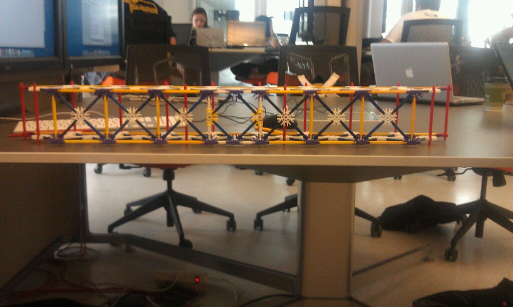
After designing, testing, and analyzing the three-foot bridge in numerous ways, the design was ready to be finalized. The final design for the bridge consisted of twenty-two main squares and each one has an “X” cross through it. Eight squares on the left side of the bridge, eight on the right of the bridge, and six on the top of the bridge. The elevation drawing (Figure 2) and plan drawing (Figure 4) of the bridge could be seen in the figure. There is an angle tilt on the two sides of the bridge which means the bottom part is longer than the top part of the bridge. The bottom part of the bridge is composed by nine 3.375” chords and the top part of the bridge is composed by seven 3.375” chords. One 360 °guest plate and four 1.25” cords consists the “X” cross in the square. In order to satisfy the constraint of leaving enough room for the vehicles to travel across, the height of the bridge is given by the length of 360°guest plate and two 1.25” cords and the width of the bridge is given by 5” long chord. These 5” chords also help to prevent the twisting of the bridge.
The design used a lot of 360°gusset plates and 180°gusset grooved plates. The 360°gusset plates help to extend the length of the bridge and joints to consist triangle of the bridge. The 180°gusset grooved plates greatly increases the possible combinations of the chords in three dimensions. But the fault of the 180°gusset grooved plates is obvious that the cost would apparently increase.
 |
| Figure 1: The Plan View of the Final Bridge |
 |
| Figure 2: Plan Drawing of the Final Bridge |
 |
Figure 3: The Elevation View of the Final Bridge
|
 |
| Figure 4: The Elevation Drawing of the Final Bridge |
 |
Figure 5: The Bill of Cost of the Final Bridge
|
Testing Results
The load at failure of the three foot bridge was a sad 28.4 pounds, 5.6 pounds less than that of the group's predicted load of 34 pounds. The bridge failed directly in the middle of the span where it was changed three times. It was as same as our hypothesis. The physical reason of the failure is the weakness of the gusset plates. The amount of designs for the top middle of the bridge was limited due to the placement of the bar in the exact middle of the bridge but the group was satisfied with the results.
Conclusions
The bridge failed exactly where all the members of the group predicted it would. The bridge 'cracked' smack in the middle of the span, which is where the group could not decide on the correct/smart design for loading the weight. The fact that the middle of the span was our downfall and we couldn't think of a way to prevent it was a heartbreaking thing to go through.
Future Work
If the group were to redesign the final bridge, it would be a sure thing that there would be a way found for the middle span of the bridge to hold the weight. Recreating the middle of the bridge would be a priority but touching up the sides would also prove beneficial for the outcome of the new test.
Tuesday, June 5, 2012
UPDATED FINAL BRIDGE
Final Bridge
After designing, testing, and analyzing the three-foot
bridge in numerous ways, the design was ready to be finalized. The final design
for the bridge consisted of twenty
two
main squares and each one has an “X” cross through it. Eight squares on the left side of the
bridge, eight on the right of the bridge, and six on the top of the bridge. The
elevation view and plan view of the bridge could be seen in the figure. There
is an angle tilt on the two sides of the bridge which means the bottom part is
longer than the top part of the bridge. The bottom part of the bridge is
composed by nine 3.375” chords and the top part of the bridge is composed by
seven 3.375” chords. One 360 °guest plate and four
1.25” cords consists the “X”
cross in the square. For satisfied the constraint that leaving enough room for
the vehicles to travel across, the height of the bridge is given by the length
of 360°guest plate and two 1.25” cords and the width of the
bridge is given by 5” long chord. These 5” chords could also prevent the
twisting of the bridge.
The design used a
lot of 360°gusset plates and 180°gusset
grooved plates. The 360°gusset plates help to extend the length
of the bridge and joints to consist triangle of the bridge. The 180°gusset grooved plates greatly increases the possible combinations of
the chords in three dimensions. But the fault of the 180°gusset grooved plates is obvious that the cost would apparently
increase.
Updated design process of A-4
Design Process
The goals set by the group were exactly that of the design parameters,
to create a working bridge of three feet of length with the lowest cost to
weight efficiency. Throughout the
course, the design of the bridge changed a few times but the goal was set in
stone since the beginning. While working
with WPBD, Truss Analysis and bridge designing, the group learned quickly as
too what would work or not. Each of
those three played an integral part in the design of the final project for the
group and it was quickly learned that in order to completely understand what goes
on when there's a bridge with a dead load (not moving) set upon it there needs
to be practice with the computer programs as well as the actual representation.
Before the class began to designing truss bridge with K’nex
pieces, they have started to work on a stimulating tool called West Point
Bridge Designer. The WPBD gave a very
in-depth understanding on the breaking point of different members of a bridge
with variable thicknesses, lengths and materials. The designer could design a bridge from lateral side of
view following specific constraints. Designer could examine the loading of the
bridge a 3-D animation truck test. If the truck has safety pass the bridge, the
bridge could be considered as a successful one. After each loading test, the
compression force and tension force would be shown in a “box”. The cost of the
bridge would also be calculated according to the size, material of members and
joints. These data can greatly help the designer to improve the design of the
truss bridge. The WPBD gave the group a
good beginning of designing a truss bridge. The group has learned how to decrease the cost
of the bridge and how to find out an optimal design. The experience that we
have learned from the WPBD helped the group to design the Knex Bridge.
The group
member individually designed three different Knex bridges in A-2. Group members used the Auto-CAD to design the
bridge in elevation view and plan view. This process helped the group to have
an idea of how to develop a bridge from two dimensions to three dimensions.
The Truss Analyses performed in and out of class were also
very helpful in that they incorporated trigonometric calculations in order to
find the load distribution on each member of the bridge. This exercise helped the group to
estimate the failing point of the bridge. The online Bridge Designer tool
inspired the group that the proportions of the triangle greatly design the loading
of the bridge. According the calculation result of the bridge, the group
decided to keep the compact design of bridge.
Building the actual
KNEX bridges gave the group a real life visual performance of the bridge
designs. By testing the Knex model in reality, the group met some problems that
would not happen in idealized stimulating tool. The twisting of bridge happened
in the loading test and had negative impact on the bridge’s performance. The
group decided to add more horizontal chords to prevent twisting of the bridge.
The final design was determined by the way the two foot
design handled the weight-test. The
three foot bridge was built with the same side designs as that of the two foot
design. The two foot bridge design was a
real extravagant piece of art, and due to the white and blue pieces primarily
chosen for the members it was so dubbed, 'The Love Train.' After the first test of the two foot bridge,
it held roughly 17 pounds, but after the addition of two more pieces and
exchanging two gusset plates, the bridge held 47 pounds. The design of the three foot span changed two
times during its design but that was after the top-middle of the span broke due
to the weakness of the joints. The
changes only made a 1-3 pound difference but any increase of weight is
accepted. The predicted load at failure
for the three foot bridge was roughly 34 pounds which was significantly lower
than the two foot span's 47 held pounds. It might due to the increasing span of the bridge.
Week 10 Post
Last week we finally tested our 36" bridge. We predicted our bridge to hold 34lbs of sand, but unfortunately it only held a tad over 28lbs. Then we did the unimaginable and took apart the great "love train" and let the bridge rest in piece. This week in class all we have to do is fill out a course evaluation sheet. I plan on giving this class a great evaluation. Before this class, however, we will be turning in our A4 report. Our major accomplishment of the week was our bridge competing against the other bridges in the class, and falling somewhere in the middle of the results in the end. There are no issues to face this week as there is no more problems I am currently trying to solve for this class. This blog post is my last issue for this class, and it is currently being resolved.
I certainly did learn something worthwhile for each of the topics identified in the course goals. Everything I did in this class was very informative and taught me something. The least beneficial part for me was the communication and availability to meet between our team. We did not really communicate too much between labs other than the blogs, and I feel like we could have been more productive in creating a better bridge had we been able to communicate and meet more. The most beneficial part for me was combining my thoughts with the thoughts of my team members and using all of our thoughts to create the bridge. It was a very enjoyable experience, and I learned a lot from it. I don't really have any suggestions on how to improve this course. I thought it was pretty close to perfect.
I certainly did learn something worthwhile for each of the topics identified in the course goals. Everything I did in this class was very informative and taught me something. The least beneficial part for me was the communication and availability to meet between our team. We did not really communicate too much between labs other than the blogs, and I feel like we could have been more productive in creating a better bridge had we been able to communicate and meet more. The most beneficial part for me was combining my thoughts with the thoughts of my team members and using all of our thoughts to create the bridge. It was a very enjoyable experience, and I learned a lot from it. I don't really have any suggestions on how to improve this course. I thought it was pretty close to perfect.
Subscribe to:
Comments (Atom)